Product Type : Ultrasonic heatmeter PCB
Product Detail:
1.Product introduction
Ultrasonic heat meter is consist of flow sensors,temperature sensors and measuring electronics modules with the the characteristics of impact construction,high accuracy,non block and easy installation. Ultrasonic heat meter are non mechanical movement,non wear and non effect from bad quality water,which can be maintained with low cost with horizontal or vertical installation(with choices)
Ultrasonic heat meter electronic module that is the key part for the ultrasonic heat meter measures the flow rate through the time difference from the inlet water and return water with measuring theultrasonic. The module can measure the instant flow rate through the temperature sensors(Pt1000), at the meanwhile, it will calculate the released heat with measurement of flow rate and temperature data.Besides,it can add the M-BUS or RS485 interface to realize the different needs for remote reading,which is can be centralized management.
1.1Technical parameter
1 Executive standard:《heat meter>>CJ128-2007;
2 M-BUS Protocol:CJ-T188-2004 / EN1434;
3 Single chip:USA TI company MSP430F4371/MSP430F4481/Etc;
4 Measuring chip:Germany ACAM company TDC-GP21、TDC-TCN,local MS1002 etc;
5 Accuracy:2
6 Working environment:4~95℃;
7 Min temperature display:0.01℃;
8 Two temperature sensors matching error:≤0.05℃;
9 Temperature difference range:0~90℃;
10 Max working pressure:1.6MPa;
11 Min heat display:0.1 kWh (user mode),0.001kWh(calibration mode);
12 Min flow rate display:0.01 m3(user mode),0.00001m3(calibration mode);
13 Total working time:h(hours);
14 History record:24 months;
15 Working environment temperature:-15~70℃;
16 Flow rate sensors: ultrasonic sensors
17 Temperature sensors: PT1000
18 Low power consumption:static working current<12μA;normal working current<25μA
1.2 Function Characteristics
1 With standard accuracy class 2 stipulated in CJ128-2007
2 high accurate measuring function:using picosecond high precision time chip, high accuracy and good stability
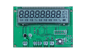
3 Display Function: Use high-resolution LCD panel displays Total heat(refrigeration), the total flow rate, instantaneous flow rate ,inlet and outlet water temperature and total working time and other information
4 Automatic data record: recording the recent 24 months history data including the total heat(refrigeration),the total flow rate , safe and reliable
5 This module can return to the user mode automatically after 3hours in the calibration mode.
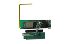
6 With infrared communication interface, which enables parameter setting, flow calibration, centralized meter reading function;
7 With M-BUS busremote function, it can realize parameter setting, flow calibration, centralized meter reading function,
8 The module can be used on many types of ultrasonic flow pipeline that can be applied to different diameter from DN15 to DN300, and better adaptability to the ultrasonic sensor, the sensors need not be paired;
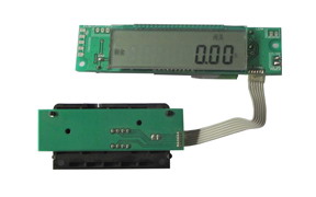
9 The electronic module is equipped with a dedicated calibration system that can achieve the parameters setting, system correction, error calculation, the derivation of original data records and other functions. At the same time, electronic modules and calibration systems are used with combination,which can make the whole process of flow testsimple, fast and efficient and can also complete three times per hour for three flow points testing or calibration.
10 Fault diagnosis, record and display functions;battery and flow rate real-time monitoring;record the date and time of valid data failure;
11 Circuits using advanced SMT surface mount technology, every piece of circuit board in the factory have dynamic current, quiescent current, M-BUS communication current, liquid crystal display, temperature,the volume of the flow, M-BUS communication, infrared communicationstestingto ensure that the products meet the technical quality requirements.
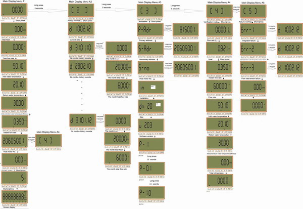
1.3 Operation instructions
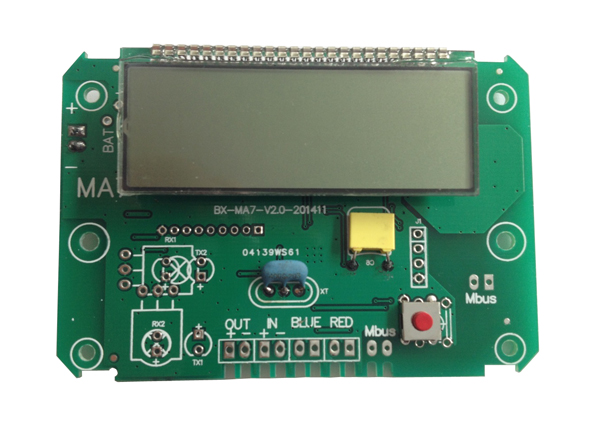
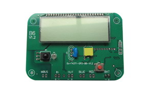
2. Wiring method
1 OUT:Outlet transducer(positive electrode+, a negative electrode-);
2 IN:inlet transducer(positive electrode+, a negative electrode-);
3 BLUE:Return temperature sensor
4 RED:Inlet temperature sensor
5 M-Bus:M-BUS interface
6 BAT + -: Power interface;
 Address: Block 2 Ruiding, Zhenhua Road No.200, Sandun, Xihu District, Hangzhou,China